HAWK-832 Project Progress Updates
Below are the progress updates for the HA-832 project. Check back regularly to see new updates.
January 16th 2026 - What just happened?
Hi folks and welcome to 2026. You're probably thinking this project is dead or may never be ready and I don't blame you for thinking that. All I can say is, life came at me and took over in 2025. So I was unable to do much at all on the project. A little progress was made with the updated hardware module. But nothing more than that. However, the good news is that 2026 is shaping up to be a much better year with the availability of more time to work on this project. This project is nowhere near dead yet. It's just taking a little longer than I hoped for.
I have had quite a few inquiries from enthusiastic Poly-800 owners asking about the upgrade kit and when it will be available. So I will make sure I add some more updates early on this year so that I can demonstrate that there is in fact forward progress with a delivery date in sight! This is as close to a "pet project" as I can imagine. So just bear with me through 2026. I think I will get it available for you all this year!
January 19th 2025 - A Scenic Detour along the Road
UPDATE: I received a couple of concerned emails from some of you worried that I was dropping the project or changing it so radically that it wasn't going to be the same huge upgrade as originally planned. Please be reassured that is not the case The exact same new and improved features of the HA-832 project are all being implemented. The change to the hardware that is explained in detail below is intended to make it easier to upgrade the Poly
without having to desolder anything at all.
Everything else pretty much stays the same. If it turns out that using the powerful STM32 CPU is somehow held back by the 80C85, then I will probably revert back to the original hardware design that requires replacing th 80C85. But I don't think that is going to be the situation. Only pre-production testing will prove that one way or the other.
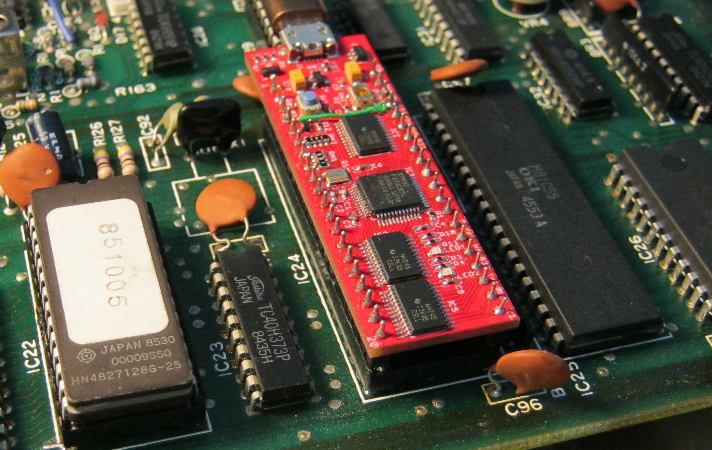
I recently damaged a Poly-800 main board while removing the 80C85 CPU from it. Not good! And I felt really bad. These synths really need to be treated better than that, Mike! And that got me thinking about how hard it will be for Poly owners to do the job themselves. I have a professional desoldering station with vacuum. So if I can damage the Poly main board while using the right tools; how easy it is going to be for others to ruin their precious synths! So I began thinking about alternatives to avoid removing the 80C85 entirely. After thinking about it for a bit, I had a bit of an "ahah!" moment and realized that I have been going about the HA832 project the wrong way yet again (good grief, not again). The HA-832 module works great but I did not need to replace the 80C85 CPU at all. Because, the 80C85 can handle the hardware and interrupts just fine. We know that already. So, I should have left the CPU right where it was. And introduced the STM32 onto the 8K EPROM socket instead. This would make it super simple to upgrade the synthesizer. Just remove the existing 2764 EPROM (27128 for the MK2) from its socket and pop the new STM32 module into the socket instead. Brilliant! Why didn't I think of this before! I mean, look at the picture of the main board below. Which should I choose? Remove 40 pin soldered in CPU (red box)? Or remove socketed EPROM and replace with 28 pin module (green box)? In retrospect, (and unless I've forgotten some reason that I can't remember), why is this even a question?

Many Moving Parts
To make this all work, the STM32 would act like a 64 byte ROM for the 80C85 with the STM32 using the EPROM chip select signal as an interrupt from the 80C85 to indicate that the 80C85 wants to read instructions or data from memory (within the 0x0000-0x003F address range). The STM32 would present the appropriate machine code onto the data bus for the 80C85 to execute. But we don't want the STM32 dishing out code and data to the 80C85 all day long. So the initial boot up (a true "boot strap") of the 80C85 would involve having the STM32 feed the 80C85 instructions and data to get the 80C85 to copy firmware (also stored in STM32 flash) over to the main onboard 2K (6116) static RAM. And then, instruct the 80C85 to execute that 2K firmware from the SRAM. At that point, the 80C85 would be executing code and accessing data within the 2K of SRAM (leaving the STM32 alone most of the time). But, the 80C85 uses ISR's (for MIDI, sequencer, and EG/MG) which rely on jump vectors that sit inside the first 64 bytes of 80C85 address space and each vector uses three consecutive bytes (call, low addr, high addr). So when the 80C85 enables its interrupts (which it read from the firmware in the 2K SRAM), it will be getting ISR vectors from that first 64 bytes of memory address space. So each time there is a hardware interrupt, the STM32 will need to serve up the call instruction and address vectors to the 80C85. However, the STM32 will "know" that the ISR's were called because of the 80C85 reads to their respective jump locations (0x002C, 0x0034, 0x003C).
What About Writes!
There's a wrinkle that we still need to deal with. The 80C85 uses separate read and write signal pins. The 2764/128 OE pin is connected to the 80C85 read line. But the write line doesn't make it to the EPROM at all (the write line is not connected to the EPROM because the EPROM is read only! It doesn't need a write signal). But to get data to the STM32 from the 80C85 requires some kind of 'write'. So that's OK, we can take address line A5 and use that as a pseudo write signal to inform the STM32 instead. This means the firmware (in the 2K SRAM) for the 80C85 will have to be written so that when the 80C85 intends to write information to the STM32, it will set A5 high (thus, reads will be at addresses 0x0000-0x003F, but writes will be 0x0040-0x007F). Once the 80C85 is running its own uploaded firmware from 2K SRAM, it will be sending control data from the STM32 out to the hardware and receiving data from the hardware and providing it back to the STM32 and signaling interrupts to the STM32. But that is all that the 80C85 will ever do. Everything else about the behavior of the synth will be handled by the STM32.
The only down side of using this solution is that the 80C85 will interrupt the STM32 three times each time it (the 80C85) gets interrupted. That's because the STM32 has serve up three bytes to the 80C85 as it (the 80C85) reads the ISR jump instructions that point the 80C85 back at the actual ISRs located in the 2K SRAM (man, this gets confusing). Those interrupts won't impose too much onto the STM32. Most of the 80C85 activity will be isolated from the STM32 entirely. Except when the 80C85 is
actually interrupted itself or needs to communicate data to/from the hardware to/from the STM32. Interestingly, the STM32 can register each of the interrupts just from those first ISR reads alone. For example, the sequencer ticks can be triggered (and then handled) within the STM32 by the simple act of the 80C85 reading memory from location 0x002C - nothing more is needed on the STM32 side of things to trigger the sequencer handler. The 80C85 though, still has to do some more 'stuff' to handle the interrupt but the STM32 doesn't need to worry about it. The read of address 0x002C triggered the STM32 to know that a sequencer tick happened. The EG/MG interrupt is similar. The MIDI interrupt is more complex than that (see the table below).
Simpler Hardware Requirements
Thus, the new module will need to have 8 x I/O for the 80C85 data bus, 6 input lines for address lines (A0-A4), 1 input line to signal writes (A6), and 2 x input lines for chip select (CS) and output enable (OE) respectively.
That's 17 lines, which is a significant reduction in the number of IO pins required compared to the existing HA-832 module.
This entire solution should fit onto a 28pin DIP instead of the 40pin HA-832. But with the reduction in IO pins down to 17, I think it should all fit along with the USB hanging off the end like the HA-832. The two LEDs would be nice to keep but are not mandatory. The reset and boot load switches are needed of course.
Perhaps we can use a different STM32 altogether. But it would need to retain the 32K SRAM and 256K flash and 72Mhz clock.
I've asked my semi-retired hardware designer/engineer if he would create this for us. Hopefully, he will do it. If not, I am going to either do it myself or find someone that can.
This solution will be an absolutely fantastic way to make this project move forward. So I am very much inclined to pursue this even though the existing HA832 moduel needs to be redesigned a fair bit. And, there will be a process of writing code to support the CPU's talking to each other and the assembler for the 80C85 to run highly efficient (fast and compact) hardware "drivers".
One last fly in the ointment. The EPROM socket that Korg used is a bit of a nightmare. It works great for a typical 28 pin chip. But does not work well for pin headers. So I need to find some pin headers that will fit into the module but also latch into the socket. If I can't find that solution then we may have to accept that the socket will have to removed and replaced with a different type. Either way, this solution is far, far better than trying to remove the 80C85. And ironically, keeping the 80C85 to do all of the support for the hardware and interrupts frees up the STM32 to do other things. Which is great!
Communication Between the CPUs
The 80C85 will need to scan the hardware for changes as well as handle interrupts. Data that it collects and happening events will need to be sent to the STM32. That will include, keyboard/front buttons/rear switches, X/Y joystick positions, received MIDI and sequencer interrupts. This can all be accomplished with the 80C85 writing one byte for each update to the STM32. Conversely, the STM32 will need to send various values, commands and statuses to the 80C85. Below is a table which is a 1st draft of the various expected messages. There will probably be some added and some in the table that need to be changed. But this is a start.
|
80C85 reading from STM32
|
|
Message Type
|
Address
|
Data/Int
|
Comments
|
|
DCO1 Volume
|
0x0008
|
8 bits
|
Sample and hold VCA
|
|
DCO2 Volume
|
0x0009
|
8 bits
|
Sample and hold VCA
|
|
Resonance
|
0x000A
|
8 bits
|
Sample and hold VCA
|
|
Noise Level
|
0x000B
|
8 bits
|
Sample and hold VCA
|
|
VCF Cutoff
|
0x000C
|
8 bits
|
Sample and hold VCA
|
|
VCF MG
|
0x000D
|
8 bits
|
Sample and hold VCA
|
|
Vibrato
|
0x000E
|
8 bits
|
Sample and hold VCA
|
|
Pitch Bend
|
0x000F
|
8 bits
|
Sample and hold VCA
|
|
DCO0 VCA0
|
0x0010
|
8 bits
|
Sample and hold VCA
|
|
DCO1 VCA1
|
0x0011
|
8 bits
|
Sample and hold VCA
|
|
DCO2 VCA2
|
0x0012
|
8 bits
|
Sample and hold VCA
|
|
DCO3 VCA3
|
0x0013
|
8 bits
|
Sample and hold VCA
|
|
DCO4 VCA4
|
0x0014
|
8 bits
|
Sample and hold VCA
|
|
DCO5 VCA5
|
0x0015
|
8 bits
|
Sample and hold VCA
|
|
DCO6 VCA6
|
0x0016
|
8 bits
|
Sample and hold VCA
|
|
DCO7 VCA7
|
0x0017
|
8 bits
|
Sample and hold VCA
|
|
Display 1
|
0x0018
|
8 bits
|
Seven segment data
|
|
Display 2
|
0x0019
|
8 bits
|
Seven segment data
|
|
Display 3
|
0x001A
|
8 bits
|
Seven segment data
|
|
Display 4
|
0x001B
|
8 bits
|
Seven segment data
|
|
Display 5
|
0x001C
|
8 bits
|
Seven segment data
|
|
Display 6
|
0x001D
|
8 bits
|
Seven segment data
|
|
Latches
|
0x001E
|
8 bits
|
Chorus,Detune,Noise Gate,Waveforms,Tape Signals
|
|
Harmonics
|
0x001F
|
8 bits
|
Tone Generator Harmonics
|
|
TG0
|
0x0020
|
7 LSB
|
Tone generator 1 note
|
|
TG1
|
0x0021
|
7 LSB
|
Tone generator 2 note
|
|
TG2
|
0x0022
|
7 LSB
|
Tone generator 3 note
|
|
TG3
|
0x0023
|
7 LSB
|
Tone generator 4 note
|
|
TG4
|
0x0024
|
7 LSB
|
Tone generator 5 note
|
|
TG5
|
0x0025
|
7 LSB
|
Tone generator 6 note
|
|
TG6
|
0x0026
|
7 LSB
|
Tone generator 7 note
|
|
TG6
|
0x0027
|
7 LSB
|
Tone generator 8 note
|
|
Command
|
0x0028
|
8 bits
|
80C85 function call (0=NOP)
|
|
Seq ISR clock tick
|
0x002C
|
RST 5.5
|
call (the 80C85 read of this byte signals a tick to STM32)
|
|
Seq ISR low addr
|
0x002D
| |
Seq ISR (byte 2 – vector low address)
|
|
Seq ISR high addr
|
0x002E
| |
Seq ISR (byte 3 – vector high address)
|
|
MIDI Rx ISR call
|
0x0034
|
RST 6.5
|
MIDI Rx ISR (byte 1 – call instruction)
|
|
MIDI Rx ISR low addr
|
0x0035
| |
MIDI Rx ISR (byte 2 – vector low address)
|
|
MIDI Rx ISR high addr
|
0x0036
| |
MIDI Rx ISR (byte 3 – vector high address)
|
|
EG/MG ISR call
|
0x003C
|
RST 7.5
|
EG/MG (2.4Khz) (byte 1 – call instruction)
|
|
EG/MG ISR low addr
|
0x003D
| |
EG/MG (2.4Khz) (byte 2 – vector low address)
|
|
EG/MG ISR high addr
|
0x003E
| |
EG/MG (2.4Khz) (byte 3 – vector high address)
|
|
80C85 writing to STM32
|
|
Message Type
|
Address
|
Data
|
Comments
|
|
MIDI Status
|
0x0040
|
8 bits
|
0=OK, 1=FIFO full (wait), 2=framing error, 3=overrun error
|
|
MIDI Received Data
|
0x0041
|
8 bits
|
80C85 has a received MIDI byte
|
|
MIDI Transmit FIFO
|
0x0042
|
1 bit
|
0=Wait (80C85 FIFO full), 1=Resume transmission
|
|
Joystick X Position
|
0x0043
|
8 bits
| |
|
Joystick Y Position
|
0x0044
|
8 bits
| |
|
Input Matrix On
|
0x0045
|
8 bits
|
Keyboard register, front buttons, rear switches (went on/enabled)
|
|
Input Matrix Off
|
0x0046
|
8 bits
|
Keyboard register, front buttons, rear switches (went off/disabled)
|
| | | | | |
| | | | | |
January 3rd 2025 - MIDI Data Reception Stops while Saving Patches or Globals to Flash Memory
The last six months of 2024 were quite hectic for me. So the development effort slowed down to a crawl. But it's 2025, and that means I have some more time on my hands. So I will be jumping right back into the development effort and hopefully, I might even have this project ready by June this year.
June 30th 2024 - MIDI Data Reception Stops while Saving Patches and Globals to Flash Memory
While I was working on the Chord and Hold poly assign modes, I discovered a problem when saving patches or globals to flash memory. MIDI data reception would stop during the flash write and would not resume either! Not good. It turns out that by default, all interrupts are ignored while the STM32 writes to flash memory. This is because read access to flash memory is blocked while flash writing is underway. And since the interrupt vector table is stored in flash, interrupts servicing is stalled until the flash write completes.
The solution requires several steps, which I go through in a separate article
here. What a major distraction this was! Now that I have that working, I'll be jumping back into the "real" code now.
June 17th 2024 - DCO Harmonics Progression, Tremolo (VCA modulation), EG Re-Triggering, LFO Delay Timers and Behavior, LFO FM and LFO PWM Modulation, and LFO Starting Phase
It has been a busy month. I have implemented a much improved harmonics modulation feature for the two DCO banks. There are 42 different harmonics progressions available which allows for some very nice melodic combinations (see the table of progressions
here).
Tremolo has also been implemented and it is expanded beyond the HAWK-800. Now you can choose from 16 different waveforms/sources and any of the six LFO's.
I have also written and tested re-triggering of the envelope generators by the LFO's. Yet to be done will be re-triggering EGs by MIDI clock and sequencer looping.
LFO delay timers have been implemented with delays of 0 to 9.9 seconds available. Also, the delay expiration has a new parameter available that allows for reseting the LFO value to initial state so that modulations are not left in an ambiguous state (a more comprehensive description to come about that later).
And, I have also completed work on the modulation of LFO frequency. In addition, I was able to implement modulation of the PWM phase. Since I don't foresee needing LFO FM and LFO PWM modulation that often, I have split those features across the odd and even LFO's.
So the LFO FM is available on LFO1 and LFO3 while the PWM modulation is available on LFO2 and LFO4.
Finally, LFO starting phase position (0, 90, 180, 270 degrees) has been implemented for all six LFOs.
May 5th 2024 - LFOs, Envelope Generators and Modulators
The major LFO waveforms (triangle, saw, sine, square PWM) are all tested and working. There was a nasty "glitchy" noise happening on note onset. That turned out to be a bug in my reseting logic of the EG3 and EG4 envelope generators. I was incorrectly reseting EG8/9 instead of EG9/10. Tooks hours to figure that one out. I've changed the modulation interrupt service routine so that most of the code is executed in the main line. The ISR simply sets a flag. The main line code then runs the modulation functions when it detects the flag is set. Due to the high speed CPU, the modulation functions are executed very soon after the flag is set. And I have a monitoring variable in place that watches for ISR flag overruns. So far, no sign of any overruns. Placing the modulation functions in main line also gives the advantage of being able to preset them at note onset which can theoretically speed up envelope generator onset speeds (even more).
Modulations are working and tested for VCF, resonance, and white noise. This includes dual modulations using LFOs or EGs, both additive and attenuative combinations. More steady progress.
April 25th 2024 - LFOs, Envelope Generators and Modulators
I made progress with the LFO's. They're now operating. Further tweaking of the envelope generators was also done and tested. The noise gate operation was implemented and tested. And the 1st modulator of the VCF has been implemented too. Steady progress.
March 24th 2024 - Note On/Off and MIDI Reception
I made progress with note on and note off actions (in Poly assign mode only) and Poly mode note on/off is now working. What a pain that was! The piano register scanner is written and implemented but not yet tested. But basic MIDI input reception is done and MIDI note on/off actions are completed and tested. The MIDI input code is now ready for implementation of pitch bend, controllers and real time messages as well.
MIDI program change is complete.
Additional progress was made with the envelope generators. I was able to implement "decay to zero" when note off occurs in the attack or decay phases (instead of using the sustain release setting). This gives added realism and flexibility to the envelopes. Speed was also improved yet again. So that now, the envelope generators are behaving much better than the original Poly-800. This is all because of the added power available with the STM32 processor.
March 10th 2024 - General 80C85 Buss, MIDI Reception and Performance Discussion
Below are three tables that provide some insight into the performance characteristics of MIDI, the 80C85 buss and the current main line code in the HAWK-832 project.
The first table shows how long it takes to receive a MIDI note on event (with no running status). It takes a tad over a millisecond. The next table shows how fast the STM32 can write to or read from the 80C85 buss hardware. It takes 4 microseconds.
The third table shows the number of 80C85 read/write instructions that occur during the main line loop in the current HAWK-832 software. At the moment, it's just 7 instructions. 7 x 4 = 28uS. This is important because the stm32 needs to have enough time to react to incoming MIDI, keyboard and joystick input, and send envelope, tone generator and MIDI out - fast. The faster the better so that the envelope generators can have very fast note onset timings. These calculations show that there is a large amount of available CPU and buss performance headroom.
It is important to note that the stm32 has to wait for accesses to/from the 80C85 buss to complete before returning back to normal operations. So although the stm32 executes instructions in nanoseconds, it has to wait 28uS in each iteration of the main loop. Fortunately, the intervening gaps in between buss access allow for the stm32 to operate at full execution speed, so there is little impact on normal operations. However, these performance parameters are very important when dealing with the critical note onset phase and high rising rates in the envelope generator phases (attack, decay etc).
With the calculations set out below, the main line code is able to react to note onset within 28uS which is very much faster than the approximate 1mS it takes just to receive a MIDI note on event. What I still need to determine is how fast I can get the envelope generators to ramp up/down (more to come on that).
|
MIDI timings
|
bps
|
1S+8N1+1mark
|
Freq
|
Period
|
MIDI byte
|
Note event (x3 bytes)
|
|
MIDI byte
|
31250
|
11
|
2840.91
|
0.000352
|
352uS
|
1,056uS (1mS)
|
| | | | | | | |
|
80C85 Buss timings
|
Frequency
|
Period
|
Time
| | | |
|
ALE (machine) cycle
|
250000
|
0.00000400
|
4uS
| | | |
|
CPU clock (ALE x3)
|
750000
|
0.00000133
|
1.33uS
| | | |
| | | | | | | |
|
Main loop 80C85 instructions
| | |
|
EG/Modulators D2A S&H
|
6
|
0.000024
|
24uS
|
io write
| | |
|
Input Scanner
|
2
|
0.000008
|
8uS
|
mem read
| | |
|
Total 80C85 instructions
|
8
|
0.000032
|
32uS
| | | |
March 10th 2024 - Envelope Generator Note Onset Performance
The envelope generators in the Poly-800 are produced by directing a digital to analog signal through a multiplexer to 8 separate sample and hold circuits. The image below is from the Poly-800 schematic and it shows those particular circuits. The red circle on the right shows the capacitor (C38) that acts as the 'hold' part of the sample and hold function (it's one of eight. One for each DCO EG). Those are 0.047uF mylar parts. The left hand circle shows R126 which is 47 ohms. That resistance, and the internal 'on' resistance within the multiplexer (IC12, a CMOS 4051) form an RC charge circuit. I believe that the 'on' resistance is 250 ohms (@5Vcc). That charge circuit is one of the factors that determines how fast (or slow) envelopes can be generated. Larger resistance or capacitance would slow down the maximum possible rate of change. Smaller values would likewise increase the maximum possible rate of change. Another factor, is the speed with which envelope levels can be setup on the D2A circuit and passed through the multiplexer. Finally, the speed of the two opamps (within IC38 TL062) would also potentially affect the maximum possible rate of change. So I am reviewing the schematic to try to determine what the theoretical maximum rate of change for the circuits are. And, I am reviewing the software performance to see how fast we can get the CPU to update the D2A. At the same time, I have ordered replacement capacitors that are half (0.022uf) and a quarter (0.013uf) of the originals. It may be a simple as replacing them like that.

March 7th 2024 - Envelope Generator Timing
Work on the envelope generators has been progressing well. At this time, I've expanded the timings that are available for use with attack, decay, slope and release. The table below shows the available timers ranging from 5 milliseconds to one minute. I would appreciate feedback from you all on whether these values are useful or how you would prefer to see them set up. The parameter values are set within the range 1-60. At the minimum value (1), the Poly-800 envelope sample and hold (SAH) circuits are pushed to the limits of their design performance (more on that soon). Obtaining a very fast note onset is extraordinarily important. So I will be trying very hard to improve on 5mS. The good news is that, from 3 (15mS) and upward, the timing accuracy of the EG's is very good. I am not sure if anyone needs an EG that extends for 60 seconds but a huge advantage of using a 32 bit CPU is the ease with which it is possible to add functionality like long timers. So providing the long duration envelope timing was easy. The table below shows the range of durations for the attack, decay, slope, and release parameters.
|
1
|
5mS
|
11
|
70mS
|
21
|
0.45 Seconds
|
31
|
2 Seconds
|
41
|
9 Seconds
|
51
|
19 Seconds
|
|
2
|
10mS
|
12
|
80mS
|
22
|
0.5 Seconds
|
32
|
2.5 Seconds
|
42
|
10 Seconds
|
52
|
20 Seconds
|
|
3
|
15mS
|
13
|
90mS
|
23
|
0.6 Seconds
|
33
|
3 Seconds
|
43
|
11 Seconds
|
53
|
22 Seconds
|
|
4
|
20mS
|
14
|
0.1 Seconds
|
24
|
0.7 Seconds
|
34
|
3.5 Seconds
|
44
|
12 Seconds
|
54
|
24 Seconds
|
|
5
|
25mS
|
15
|
0.15 Seconds
|
25
|
0.8 Seconds
|
35
|
4 Seconds
|
45
|
13 Seconds
|
55
|
26 Seconds
|
|
6
|
30mS
|
16
|
0.2 Seconds
|
26
|
0.9 Seconds
|
36
|
4.5 Seconds
|
46
|
14 Seconds
|
56
|
28 Seconds
|
|
7
|
35mS
|
17
|
0.25 Seconds
|
27
|
1 Second
|
37
|
5 Seconds
|
47
|
15 Seconds
|
57
|
30 Seconds
|
|
8
|
40mS
|
18
|
0.3 Seconds
|
28
|
1.25 Seconds
|
38
|
6 Seconds
|
48
|
16 Seconds
|
58
|
40 Seconds
|
|
9
|
50mS
|
19
|
0.35 Seconds
|
29
|
1.5 Seconds
|
39
|
7 Seconds
|
49
|
17 Seconds
|
59
|
50 Seconds
|
|
10
|
60mS
|
20
|
0.4 Seconds
|
30
|
1.75 Seconds
|
40
|
8 Seconds
|
50
|
18 Seconds
|
60
|
1 Minute
|
February 28th 2024
A quick update on new navigating and patch editing features:
- Button Repeating - The keypad buttons and Program/Parameter buttons all repeat when held down. Just like the existing parameter value up/down buttons. This should help a little bit with the constant button bashing that happens when working with the Poly-800.
- Independent Bank Hold - Each of the four modes (program select, and parameter bank selects P2, P3, and Global/P4) all retain their bank hold states independently of each other.
- Independent Parameter Bank Selected Values - Also for each of the four modes, each retains their own selected parameter number values. This makes it easier to navigate through the parameters.
- Program Most Significant Digit Increment/Decrement while Bank Hold is Enabled - Program select bank hold allows most significant digit selection using up/down buttons. This one is a little obscure and may not be particularly useful. I'll keep or drop it depending upon user feedback.
- The three features above are all intended to improve the ease of programming the Poly 800. If you think they would make things harder, more confusing, or otherwise problematic, do please let me your thoughts.
- Save Global Parameters save the global parameters by pressing the Write Button and then pressing the Bank Hold Button. Globals are NOT saved when a patch is saved.
- Lock/Unlock Patch allows blocking the editing or overwriting of each patch.
- Save a Patch into Another Patch in a Different Patch Bank - This is a nine step process so it's about as hard as it gets. Here goes:
There is a patch (the source patch) that you intend to use for editing and then want to save it to a patch in a different patch bank (the destination patch).
First, (and before you start editing any patch) make sure that the destination patch is unlocked:
Step 1) Go to global mode and select the bank (1-4) of the destination patch.
Step 2) Go to program select mode and punch in the destination patch number (11-88).
Step 3) Go to parameter mode P3, select parameter 88, and set the data value to zero (patch unlocked). Then press the write button (patch is now saved unlocked).
Second, go to the source patch (now you can do your editing as desired):
Step 4) Go to global mode and select the bank (1-4) of the source patch.
Step 5) Go to program select mode and punch in the source patch number (11-88). The source patch is the patch that you wish to edit/copy before copying it to the destination patch.
Step 6) Make any desired edits to the source patch.
Third, write the source patch to the destination patch:
Step 7) Go to global mode and select the bank (1-4) of the destination patch.
Step 8) Go to program select mode and press the write button.
Step 9) Then punch in the destination patch number (11-88).
When the write completes, the current selected patch will be the destination patch. If you try to write to a destination patch that is locked, the write will fail and write mode will display flashing two bars "--". You can then punch in a different patch to write to or press the write button again to cancel the write.
Note that after the write (successful or cancelled) the patch bank is still set to the destination. So don't forget to select the desired patch bank again (another step!).
February 24th 2024
I've made some progress with the user input (keypad and buttons) handlers and have some of the patch and parameter selection and editing working. Before I proceed further into that part of the code, I worked up a table that shows the proposed patch parameters and global parameters for the HAWK-832.
The table is shown below. Many of the parameters are taken from the HAWK-800, which in turn are taken from the original Poly-800. There are so many new parameters in the HAWK-832 that they will have to be handled in P1, P2, P3 and GL/P4 user input modes. Please feel free to review the parameters and provide feedback.
Keep in mind that whether a parameter (and thus, feature) makes it into the finished product depends on it being viable to implement. So for example, I plan on implementing six LFO's (4 LFO and 2 SLFO) and four envelope generators (which in practice actually means 10. 8 for each voice and two to act as operators.
If it can be managed, I would even like to add another fifth envelope generator. We shall see. It will be necessary to perform testing during the implementation to see if all of those operators can be implemented while also maintaining a high performance profile. One of the drawbacks of the original Poly-800 and HAWK-800 are the sluggish attack/decay waveforms and the variable timings at note onset. First and foremost, it will be crucial that we get excellent EG waveforms and fast, responsive note onset. Additional LFO's and EG's are of secondary importance.
UPDATE June 19th 2024 - the table below shows the current parameter list.
|
P1
|
DCO1
| |
DCO2
| |
DCO VCA and Detune
| |
EFX
| |
EG1 (DCO1)
| |
EG2 (DCO2)
| |
EG3
| |
EG4
| |
|
11
|
Octave
|
21
|
Octave
|
31
|
DCO1 Mod Source
|
41
|
EFX delay time
|
51
|
Attack
|
61
|
Attack
|
71
|
Attack
|
81
|
Attack
| |
|
12
|
Waveform
|
22
|
Waveform
|
32
|
DCO1 Mod LFO
|
42
|
EFX feedback
|
52
|
Decay
|
62
|
Decay
|
72
|
Decay
|
82
|
Decay
| |
|
13
|
Harmonics
|
23
|
Harmonics
|
33
|
DCO1 Mod Depth
|
43
|
EFX mod freq
|
53
|
Break point
|
63
|
Break point
|
73
|
Break point
|
83
|
Break point
| |
|
14
|
Harmonics Modulation Sequence
|
24
|
Harmonics Modulation Sequence
|
34
|
DCO2 Mod Source
|
44
|
EFX mod intensity
|
54
|
Slope
|
64
|
Slope
|
74
|
Slope
|
84
|
Slope
| |
|
15
|
Harmonics Modulation LFO
|
25
|
Harmonics Modulation LFO
|
35
|
DCO2 Mod LFO
|
45
|
EFX level
|
55
|
Sustain
|
65
|
Sustain
|
75
|
Sustain
|
85
|
Sustain
| |
|
16
|
-
|
26
|
-
|
36
|
DCO2 Mod Depth
|
46
|
MK2 EQ Bass
|
56
|
Release
|
66
|
Release
|
76
|
Release
|
86
|
Release
| |
|
17
|
Level
|
27
|
Level
|
37
|
DCO2 Interval
|
47
|
MK2 EQ Treble
|
57
|
-
|
67
|
-
|
77
|
Keyboard Trigger
|
87
|
Keyboard Trigger
| |
|
18
|
DCO Mode
|
28
|
Key Assign Mode
|
38
|
DCO2 Detune
|
48
|
Chorus Mode
|
58
|
Other Trigger
|
68
|
Other Trigger
|
78
|
Other Trigger
|
88
|
Other Trigger
| |
|
P2
|
LFO1
| |
LFO2
| |
LFO3
| |
LFO4
| |
SLFO 5/6
| |
LFO
| |
LFO
| |
Velocity
| |
|
11
|
Frequency
|
21
|
Frequency
|
31
|
Frequency
|
41
|
Frequency
|
51
|
SLFO5 Frequency
|
61
|
LFO1 Start Phase
|
71
|
LFO1 Freq Kybd Track
|
81
|
OP1 Intensity
| |
|
12
|
Delay
|
22
|
Delay
|
32
|
Delay
|
42
|
Delay
|
52
|
SLFO5 PWM Phase
|
62
|
LFO2 Start Phase
|
72
|
LFO2 Freq Kybd Track
|
82
|
OP1 Invert
| |
|
13
|
Delay Invert
|
23
|
Delay Invert
|
33
|
Delay Invert
|
43
|
Delay Invert
|
53
|
SLFO5 Reset
|
63
|
LFO3 Start Phase
|
73
| |
83
|
OP1 Target
| |
|
14
|
Reset
|
24
|
Reset
|
34
|
Reset
|
44
|
Reset
|
54
|
SLFO5 Start Phase
|
64
|
LFO4 Start Phase
|
74
| |
84
|
OP2 Intensity
| |
|
15
|
PWM Phase
|
25
|
PWM Phase
|
35
|
PWM Phase
|
45
|
PWM Phase
|
55
|
SLFO6 Frequency
|
65
|
LFO1 Clock Source
|
75
| |
85
|
OP2 Invert
| |
|
16
|
FM Waveform
|
26
|
PWM Mod Waveform
|
36
|
FM Waveform
|
46
|
PWM Mod Waveform
|
56
|
SLFO6 PWM Phase
|
66
|
LFO2 Clock Source
|
76
| |
86
|
OP2 Target
| |
|
17
|
FM LFO
|
27
|
PWM Mod LFO
|
37
|
FM LFO
|
47
|
PWM Mod LFO
|
57
|
SLFO6 Reset
|
67
|
LFO3 Clock Source
|
77
| |
87
|
VCF Intensity
| |
|
18
|
FM Depth
|
28
|
PWM Mod Depth
|
38
|
FM Depth
|
48
|
PWM Mod Depth
|
58
|
SLFO6 Start Phase
|
68
|
LFO4 Clock Source
|
78
| |
88
|
VCF Shape
| |
|
P3
|
Set Points
| |
DCO Freq Mod
| |
VCF Mod
| |
Resonance Mod
| |
Noise Mod
| |
Sequencer
| |
ARP & Misc
| |
Misc
| |
|
11
|
VCF
|
21
|
1st Modulation Waveform
|
31
|
1st Modulation Waveform
|
41
|
1st Modulation Waveform
|
51
|
1st Modulation Waveform
|
61
|
-
|
71
|
ARP Length
|
81
|
Bend Depth
| |
|
12
|
Resonance
|
22
|
1st Modulation LFO
|
32
|
1st Modulation LFO
|
42
|
1st Modulation LFO
|
52
|
1st Modulation LFO
|
62
|
-
|
72
|
ARP Direction
|
82
|
Portamento Rate
| |
|
13
|
Noise
|
23
|
1st Modulation Depth
|
33
|
1st Modulation Depth
|
43
|
1st Modulation Depth
|
53
|
1st Modulation Depth
|
63
|
-
|
73
|
ARP Range
|
83
|
Pedal Mode
| |
|
14
|
<DCO3 New TG>
|
24
|
2nd Modulation Waveform
|
34
|
2nd Modulation Waveform
|
44
|
2nd Modulation Waveform
|
54
|
2nd Modulation Waveform
|
64
|
-
|
74
|
ARP Sort
|
84
|
Pedal Sustain Offset
| |
|
15
|
<DCO4 New TG>
|
25
|
2nd Modulation LFO
|
35
|
2nd Modulation LFO
|
45
|
2nd Modulation LFO
|
55
|
2nd Modulation LFO
|
65
|
Selected Sequence
|
75
|
ARP As Played
|
85
|
-
| |
|
16
|
-
|
26
|
2nd Modulation Depth
|
36
|
2nd Modulation Depth
|
46
|
2nd Modulation Depth
|
56
|
2nd Modulation Depth
|
66
|
Sequencer ¼ Note RSH
|
76
|
-
|
86
|
-
| |
|
17
|
-
|
27
|
Modulation Mode
|
37
|
Modulation Mode
|
47
|
Modulation Mode
|
57
|
Modulation Mode
|
67
|
Sequencer Loop RSH
|
77
|
-
|
87
|
-
| |
|
18
|
-
|
28
|
Modulation Send
|
38
|
Keyboard Tracking
|
48
|
Keyboard Tracking
|
58
|
Keyboard Tracking
|
68
|
Seq Note Follow Mode
|
78
|
-
|
88
|
Patch Locked
| |
|
GL
|
General
| |
Sequences
|
P4
|
MIDI
| |
MIDI
| |
MIDI Clocks
| |
<Growth>
| |
<Growth>
| |
<Growth>
| |
|
11
|
Selected Patch
|
21
|
Protect Sequence 1
|
31
|
MIDI Receive Channel
|
41
|
Seq MIDI Tx Channel
|
51
|
MIDI Clock 1
|
61
|
<New TG>
|
71
|
<New TG>
|
81
|
<New TG>
| |
|
12
|
Selected Bank
|
22
|
Protect Sequence 2
|
32
|
MIDI Soft Thru
|
42
|
Seq Time Code Send
|
52
|
MIDI Clock 2
|
62
|
<New TG>
|
72
|
<New TG>
|
82
|
<New TG>
| |
|
13
|
NRPN MSB Device Identification
|
23
|
Protect Sequence 3
|
33
|
Kbd Local Control
|
43
|
Seq Ticks per quarter note
|
53
|
MIDI Clock 3
|
63
|
<New TG>
|
73
|
<New TG>
|
83
|
<New TG>
| |
|
14
|
Scaled/Absolute CC data
|
24
|
Protect Sequence 4
|
34
|
Kbd MIDI Tx Channel
|
44
|
Advanced Seq Mode
|
54
|
MIDI Clock 4
|
64
|
<New TG>
|
74
|
<New TG>
|
84
|
<New TG>
| |
|
15
|
Omni On/Off
|
25
|
Protect Sequence 5
|
35
|
Kbd MIDI Tx Octave Offset
|
45
|
Seq Clock Int/Ext
|
55
|
Seq Clock 1
|
65
|
<New TG>
|
75
|
<New TG>
|
85
|
<New TG>
| |
|
16
|
Cascading Mode
|
26
|
Protect Sequence 6
|
36
|
Kbd MIDI Tx Velocity
|
46
|
Joystick Local Control
|
56
|
Seq Clock 2
|
66
|
<New TG>
|
76
|
<New TG>
|
86
|
<New TG>
| |
|
17
|
Cascading Unit Sync
|
27
|
Protect Sequence 7
|
37
|
Selected Sequence
|
47
|
Joystick MIDI Tx Channel
|
57
|
Seq Clock 3
|
67
|
<New TG>
|
77
|
<New TG>
|
87
|
<New TG>
| |
|
18
|
Device Type
|
28
|
Expansion Hardware
|
38
|
Seq Local Control
|
48
|
MIDI Bank Select Patch Change
|
58
|
Seq Clock 4
|
68
|
<New TG>
|
78
|
<New TG>
|
88
|
<New TG>
| |
February 2024
So before beginning the task of rewriting the entire Poly-800 software in C. I figured I had better break down the effort into stages so that I can monitor progress along the way. Here are the major project steps:
Major Project Milestones and Activities
- Initial Design and Feasibility Study (2019)
- Hardware Prototype Development (2019 and 2020)
- Develop the HAL Firmware (mostly done in 2023)
- Prove out performance (mostly done in 2023)
- Finalize Hardware Design/HAL (prototype checked out in 2023)
- Flash Memory Read/Write Operations - flash.c (January/February 2024). Because flash memory is the last piece of the hardware puzzle.
- User Interface - userin.c, global.c, patch.c. Getting the basic input/output working will help with all of the other tasks.
- Running Patch Management - patch.c. Being able to copy and edit patches will be crucial in testing the sound generation features.
- Sound Generation - lfo.c, envelope.c, velocity.c, polyMain.c, eg_mg (various).
- Sound Operation - userin.c
- MIDI General Operation - midiin.c
- MIDI Note Operation - midinote.c
- MIDI Controller Operation - midicc.c
- MIDI System Exclusives - sysex.c
- Arpeggiator - arp.c
- Sequencer - seq.c
- Unit Testing
- Beta Testing
- Kit Manufacture
- Documentation
- General Product Release
As can be seen above, the number and types of activities is significant. And the sheer number of lines of code that need to be re/written makes this project less than trivial. But at this point in time, I am hoping that I can complete the entire project in no more than 500 hours. If that time estimate is correct, and at 10 hours per week, that will take the project into early 2025. If I am lucky, the 500 hours estimate is more than enough. In which case, I might even be able to have the kit ready for Christmas 2024. It would be great if I could have it ready in December 2024.
January 2024
All of the the HAWK-832 interfacing to the Poly800 hardware has been proven out in testing (excluding the sequencer/arpeggiator clock interrupt which has to wait until I get updated HAWK-832 modules to work with. The prototype modules I am working with now can't work with the sequencer interrupt due to a timer mapping problem that required rerouting the sequencer interrupt pin). And I now have working analog to digital operation and envelope generator signal generation. At this time, I'm assessing the work program to decide which components of the software will be developed next. Once the list of modules is developed, I'll post them here. I am also toying with the idea of posting the code onto github so that other contributors can help to speed up the software development process. If you would like to help, contact Mike at support@hawk800.com.
Now that the hardware is almost 100% proven, I can proceed to the major part of the project, which is to forward engineer the assembler into C.
2023
Development activity restarted in mid 2023. Internal use of STM32 CPU hardware includes using TIM2 ISR for the EG's. EXT15 ISR sampling pins 15 and 14 for MIDI and Sequencer. TIM19 (no ISR) for ALE pin and for CPU machine cycle timing. TIM4 (no ISR) for 68B50 MIDI UART clock. This all works and is the point at which hardware testing is completed. However, the 68B50 and SOD pins need to be swapped and the board updated. Fortunately, coding can proceed on everything except the sequencer while new boards are ordered and populated. Coding of the synth is commencing.
Before I do that though, I needed to consider the best method for proceeding to code. The three options then, are to:
1) mentally disassemble the assembler and convert into C
2) rewrite the entire code directly in C
3) create a JIT compiler (in C) that compiles 80C85 assembler
I have decided to rewrite the existing assembler into C. It turns out that I am able to 'forward' engineer assembler into C reasonably well. It helps alot that my documentation in the assembler is very detailed. So the method will be sort of a combination of option 1 and option 2. Some of the code will be migrated from assembler to C and some of it will be a complete rewrite. How much of each really depends on the part of the code. For example, the flash memory subroutines will have to be completely rewritten from scratch because the hardware is completely different. Also, all of the interrupt service routine code will have to be done from scratch. But alot of the rest of the code can be migrated.
2021/2022
No development activity occurred in 2021 or 2022.
2020
Prototypes were created and initial efforts to begin software development and prototype testing were underway. A problem was found with the address bus latch signals which stopped the prototype from working on the 80C85 bus. The design was corrected and new boards ordered, populated and tested.
2019
The HAWK-832 prototype was first developed on 'paper' in late 2019. No prototypes were created until April 2020.